DIY bicycle speedometer: A final update on the bicycle speedometer project, this time I made it work. After assembling the PCB and most of the outer shell, as seen here, I then set out to install the speedometer in my bicycle and went for a ride.
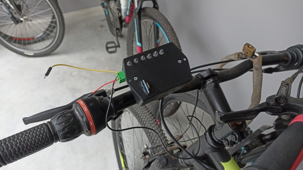
You can see at the picture above the speedometer mounted in my bicycle. As previously stated, I bought a commercial speedometer just for parts. I got the sliding mount pad from it, and glued it to my black box. The yellow and red wires you see in the picture are the battery (+) wire, for me to be able to turn the system off.
The black double wire is from the reed switch sensor on the wheel. TP4056’s USB is seen in the bottom left side of the box, and is for battery charging. I never have to open the box, since the green reed switch sensor connector is dettachable. That is part of the DIY bicycle speedometer.
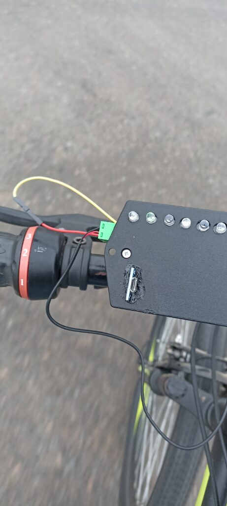
I selected green LEDs for the display since they are supposedly the ones more visible under sunslight. As stated here “Green, the mixture of blue and yellow, can be seen everywhere and in countless shades. In fact, the human eye sees green better than any color in the spectrum”.
But in fact as seen in the picture below, the LED were barely visible at all. This is even under overcast weather. If you really want to see, look at the second LED from left to right, it is lit. For the human eye it is just fine to look at the speedometer display, you can easily see the lit LED.
The first test
When I first set to got outside and test the odomer, it was not lighting any LED over 20 km/h. It was just controlling the first three (5, 10, 10 km/h) LEDs. I first thought that the reed sensor switch would not be fast enough to read such speeds. But then I remembed that I bought a commercial speedometer and took the sensor from it. It had to work.
I then checked the RC filter I put in the sensor input at my PCB, and sure enough there was the error. I had put a 1uF capacitor as C2, which is surely too high for such “high” sensor detection speeds.
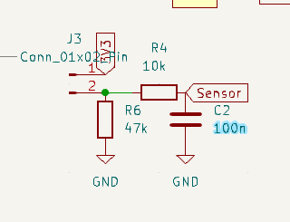
I then came back home, opened the speedometer box and replaced C2 by a 100nF one. Surely enough when I went back to the road for testing the speedometer lit every LED, from >5km/h (LED1) all the way to >30km/h (LED6). I used this tool to calculate such filter. But what i did no take into account was that a 1uF capacitor takes its time to discharge. This effectively made the last cycle mess the next one, and so on.
Here is a video of the first test, even if you cannot see any LED lit, rest assure they were doing their thing.
DIY bicycle speedometer
As stated in previous updates, the code for this speedometer was simple enough that I made it in one afternoon. Assembling it went smooth (of course thanks to my skill in designing the board). Testing it was quick, I just had to replace a capacitor and have it to work.
See you next time! if you have any question please use the comments section below or look for me on LinkedIn.


