RP2040 Lora: go to the next level in communications for Arduino, using this Waveshares RP2040 LoRa controller. Stick with me and learn how to do just that.
Blinking an LED
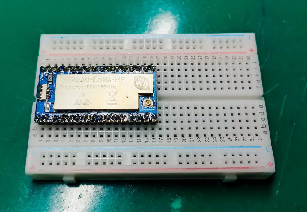
The most classical way of testing a microcontroller board is to blink an LED. With this Waveshare RP2040 Lora board I will pick a random pin (D21) and use the “BlinkWithoutDelay” code available in the Arduino IDE.
// constants won't change. Used here to set a pin number:
const int ledPin = D21;  // the number of the LED pin

// Variables will change:
int ledState = LOW;  // ledState used to set the LED

// Generally, you should use "unsigned long" for variables that hold time
// The value will quickly become too large for an int to store
unsigned long previousMillis = 0;  // will store last time LED was updated

// constants won't change:
const long interval = 200;  // interval at which to blink (milliseconds)

void setup() {
  // set the digital pin as output:
  pinMode(ledPin, OUTPUT);
}

void loop() {
  // here is where you'd put code that needs to be running all the time.

  // check to see if it's time to blink the LED; that is, if the difference
  // between the current time and last time you blinked the LED is bigger than
  // the interval at which you want to blink the LED.
  unsigned long currentMillis = millis();

  if (currentMillis - previousMillis >= interval) {
    // save the last time you blinked the LED
    previousMillis = currentMillis;

    // if the LED is off turn it on and vice-versa:
    if (ledState == LOW) {
      ledState = HIGH;
    } else {
      ledState = LOW;
    }

    // set the LED with the ledState of the variable:
    digitalWrite(ledPin, ledState);
  }
}
The result is seen in the gif video below, an LED on pin 21 blinking every 200ms.
Testing out the HMC5883L magnetometer
For show purposes we will be testing the HMC5883L magnetometer, that works via i2c communication. The first thing we have to do is find out the HMC5883L chip i2c address. For that we will use the i2c scanner code. My module is at 0x1E.
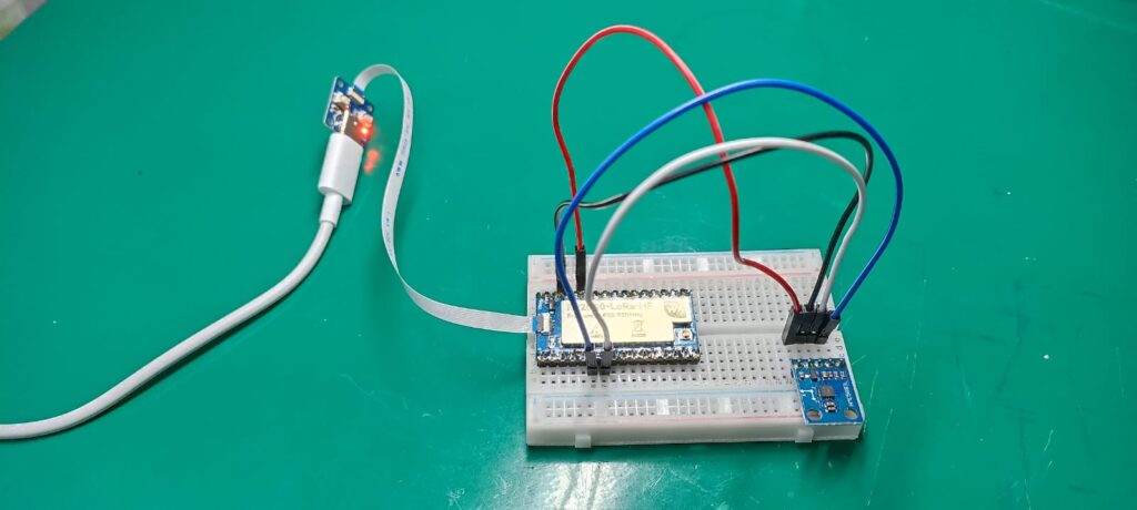
You can see below the complete circuit we will be using, already assembled. Notice in the lower right corner of the breadboard the HMC5883L magnetometer chip. The RP2040 Lora module receives USB/serial communication via a flat cable. Not the best idea in my opinion, but that is up to the manufacturer, Waveshare.
Upon running the i2c scanner and trying to figure the HMC5883L address I stuble in a problem. The Waveshare RP2040-Lora-HF can have the i2c and SPI be in various pin, configurable. But the Arduino Wire library does not allow me to change such pin. So I had to excursion from pair to pair of i2c pins, until I made it work on pins GP4 (SDA) and GP5 (SCL).
It could be a coincidence that on the Arduino UNO board the i2c is at A4 and A5. Look at the RP2040-Lora-HF pinout below.
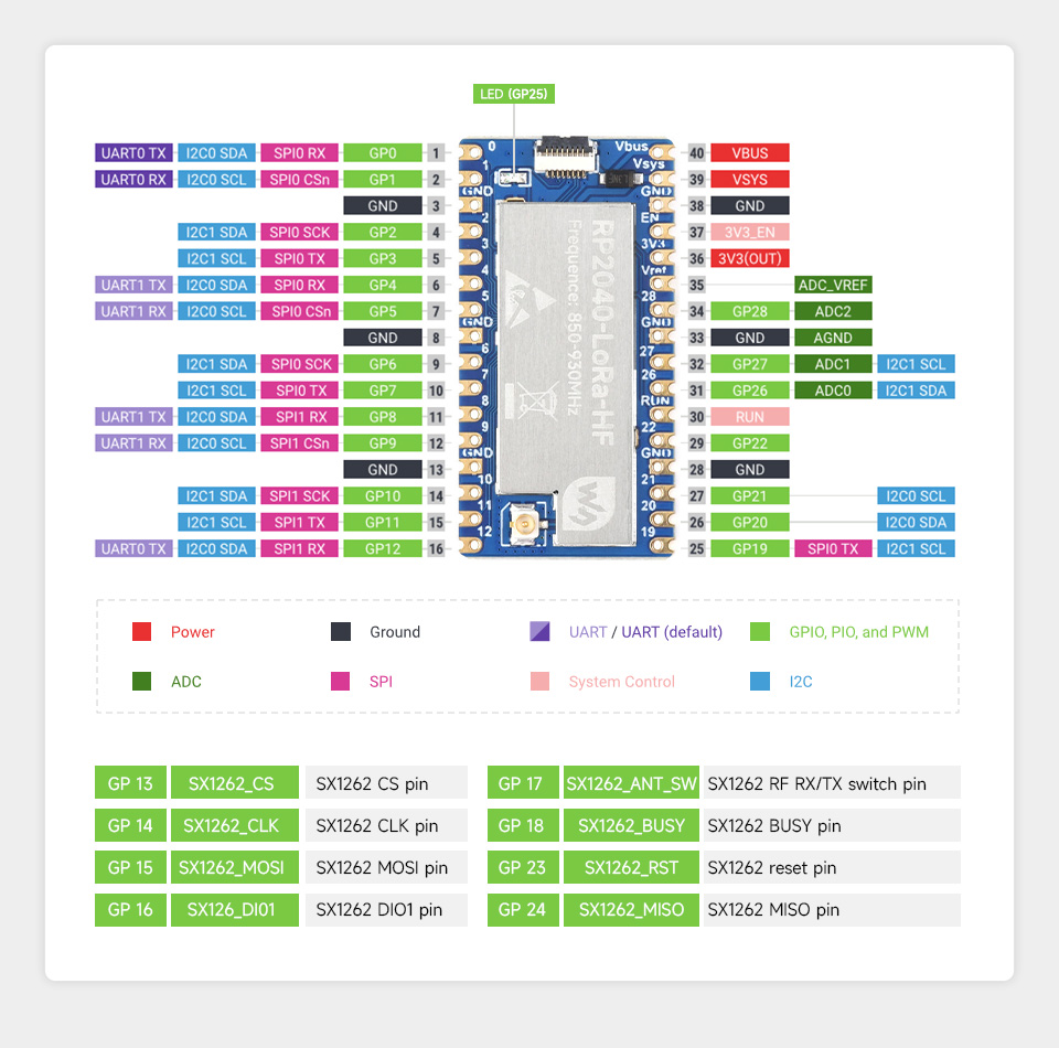
Notice tha i2C0 can be at 0/1 or 4/5 or 8/9 or 12/19 or 20/21. After figuring the module address, I run the code below which is from the example at the official Adafruit library. You can install this library in the Arduino IDE by going to “Sketch > Include library > Manage libraries” and typing “HMC5883L Adafruit”.
The example code will then be at “File > Examples > Adafruit HMC5883 unified > Magsensor.ino”.
#include <Wire.h>
#include <Adafruit_Sensor.h>
#include <Adafruit_HMC5883_U.h>

/* Assign a unique ID to this sensor at the same time */
Adafruit_HMC5883_Unified mag = Adafruit_HMC5883_Unified(12345);

void displaySensorDetails(void)
{
  sensor_t sensor;
  mag.getSensor(&sensor);
  Serial.println("------------------------------------");
  Serial.print  ("Sensor:       "); Serial.println(sensor.name);
  Serial.print  ("Driver Ver:   "); Serial.println(sensor.version);
  Serial.print  ("Unique ID:    "); Serial.println(sensor.sensor_id);
  Serial.print  ("Max Value:    "); Serial.print(sensor.max_value); Serial.println(" uT");
  Serial.print  ("Min Value:    "); Serial.print(sensor.min_value); Serial.println(" uT");
  Serial.print  ("Resolution:   "); Serial.print(sensor.resolution); Serial.println(" uT");
  Serial.println("------------------------------------");
  Serial.println("");
  delay(500);
}

void setup(void)
{
  Serial.begin(9600);
  Serial.println("HMC5883 Magnetometer Test"); Serial.println("");

  /* Initialise the sensor */
  if(!mag.begin())
  {
    /* There was a problem detecting the HMC5883 ... check your connections */
    Serial.println("Ooops, no HMC5883 detected ... Check your wiring!");
    while(1);
  }

  /* Display some basic information on this sensor */
  displaySensorDetails();
}

void loop(void)
{
  /* Get a new sensor event */
  sensors_event_t event;
  mag.getEvent(&event);

  /* Display the results (magnetic vector values are in micro-Tesla (uT)) */
  Serial.print("X: "); Serial.print(event.magnetic.x); Serial.print("  ");
  Serial.print("Y: "); Serial.print(event.magnetic.y); Serial.print("  ");
  Serial.print("Z: "); Serial.print(event.magnetic.z); Serial.print("  ");Serial.println("uT");

  // Hold the module so that Z is pointing 'up' and you can measure the heading with x&y
  // Calculate heading when the magnetometer is level, then correct for signs of axis.
  float heading = atan2(event.magnetic.y, event.magnetic.x);

  // Once you have your heading, you must then add your 'Declination Angle', which is the 'Error' of the magnetic field in your location.
  // Find yours here: http://www.magnetic-declination.com/
  // Mine is: -13* 2' W, which is ~13 Degrees, or (which we need) 0.22 radians
  // If you cannot find your Declination, comment out these two lines, your compass will be slightly off.
  float declinationAngle = 0.22;
  heading += declinationAngle;

  // Correct for when signs are reversed.
  if(heading < 0)
    heading += 2*PI;

  // Check for wrap due to addition of declination.
  if(heading > 2*PI)
    heading -= 2*PI;

  // Convert radians to degrees for readability.
  float headingDegrees = heading * 180/M_PI;

  Serial.print("Heading (degrees): "); Serial.println(headingDegrees);

  delay(500);
}
The result
Opening the Arduino IDE’s serial monitor will result in something like the image below.
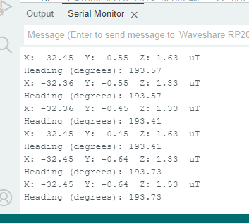
By spinning the breadboard in the table surface one can obtain an approximate angle related to the true magnetic north. In fact any orientation change will result in the X, Y and Z numbers changing. Applications where one needs to know the magnetic north would great benefit from the HMC5883L magnetometer.
RP2040 Lora
The Waveshare’s RP2040-Lora-HF is a neat little module based on the RP2040 Raspberry Pi chip. It also contains a Lora transceiver called SX1262. I was still not able to make the Lora work, but will keep trying and keep you posted.
Meanwhile if you want to buy the Waveshare RP2040-Lora-HF click here. Please be advised to choose the one with the frequency that can be legally used in your country.


I am also having issues with getting the LoRa module to work.
If you succeed, please let me know!
Sure, will do
Kindly contact me i am facing issue configuring the lora2040 waveshare HF Model
+923196051338 whatsapp