The power of interrupts: Let’s study ESP32 interrupts in Arduino IDE, both of them (timer ones and external ones). Our subject will be my dev board (info here) featuring a Xiao ESP32-C6. There is official support for both interrupt modes for ESP32-C6 on the Arduino IDE. So our life is a little easier.
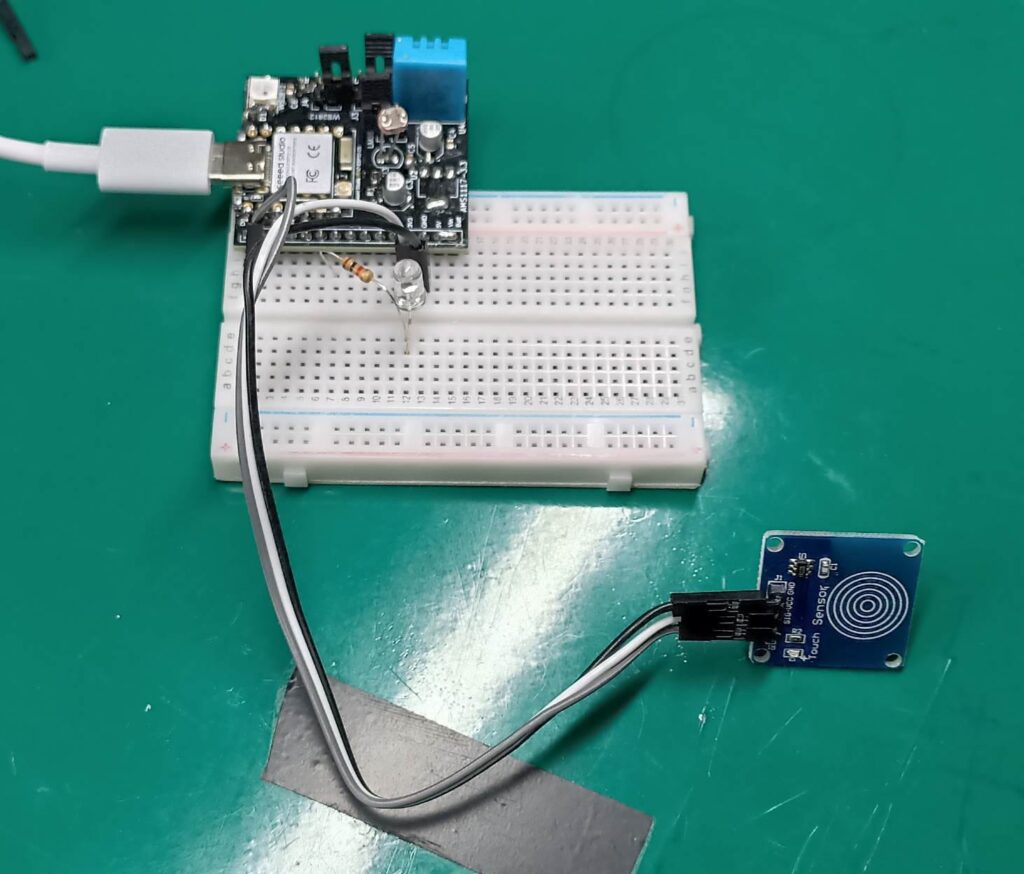
Above you can see the whole setup we will be using for this article, an LED on pin D6 and a capacitive touch button on pin D0.
Hardware interrupts
Starting by the hardware interrupts, I was not able to find the information on which pins are to be used as hardware interrupts. The only info I found is that on ESP32 “any pins” will work as interrupts. I then proceeded to connect a capacitive touch button to pin D0 and it worked.
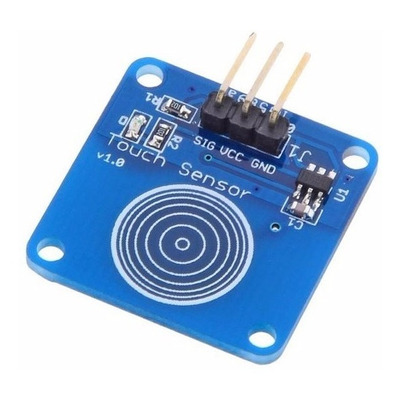
The capacitive touch sensor is one fo these of the picture above, which can be bought from here. It outputs a logic level HIGH (3V3) with a touch and a logic level LOW (0V) without touch.
The code is seen below, taken and adapted from this source. It waits for an activation of pin D0 and prints the number of touchs so far at the serial monitor.
// code from here https://lastminuteengineers.com/handling-esp32-gpio-interrupts-tutorial/
struct Button {
const uint8_t PIN;
uint32_t numberKeyPresses;
bool pressed;
};
Button button1 = {D0, 0, false};
void IRAM_ATTR isr() {
button1.numberKeyPresses++;
button1.pressed = true;
}
void setup() {
Serial.begin(115200);
pinMode(button1.PIN, INPUT_PULLUP);
attachInterrupt(button1.PIN, isr, RISING);
}
void loop() {
if (button1.pressed) {
Serial.printf("Button has been pressed %u times\n", button1.numberKeyPresses);
button1.pressed = false;
}
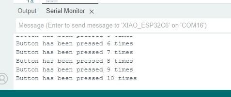
}The serial monitor output is seen below, pretty simple. Shows the number of times (cumulative) that the sensor button was pressed.
The part of code below is where the interruption is threated, a counter is incremented and a varible (button pressed) goes to high. IRAM_ATTR is the way interrupts are handled in ESP32, don’t ask.
void IRAM_ATTR isr() {
	button1.numberKeyPresses++;
	button1.pressed = true;

}
Timer interrupts
ESP32-C6 has two timers which can be used to cause/handle interrupts. For this one I used the Espressif’s official Wiki as an inspiration. it contains an example of the timer interrupt with a stop button, to cease its operation. I confess I disabled that “stop” part of the code because it was stopping right after hitting program.
This is effectively the power of interrupts. I added an LED so that we can see the timer doing its thing, blinking the LED. There is also serial monitor activity to be seen. The code is rather long as is seen below.
// official ESpressif example from here https://espressif-docs.readthedocs-hosted.com/projects/arduino-esp32/en/latest/api/timer.html
/*
 Repeat timer example

 This example shows how to use hardware timer in ESP32. The timer calls onTimer
 function every second. The timer can be stopped with button attached to PIN 0
 (IO0).

 This example code is in the public domain.
 */

// Stop button is attached to PIN 0 (IO0)
#define BTN_STOP_ALARM    D0
#define LED D6

hw_timer_t * timer = NULL;
volatile SemaphoreHandle_t timerSemaphore;
portMUX_TYPE timerMux = portMUX_INITIALIZER_UNLOCKED;

volatile uint32_t isrCounter = 0;
volatile uint32_t lastIsrAt = 0;

void ARDUINO_ISR_ATTR onTimer(){
  // Increment the counter and set the time of ISR
  portENTER_CRITICAL_ISR(&timerMux);
  isrCounter = isrCounter + 1;
  lastIsrAt = millis();
  portEXIT_CRITICAL_ISR(&timerMux);
  // Give a semaphore that we can check in the loop
  xSemaphoreGiveFromISR(timerSemaphore, NULL);
  // It is safe to use digitalRead/Write here if you want to toggle an output
}

void setup() {
  Serial.begin(115200);

  // Set BTN_STOP_ALARM to input mode
  pinMode(BTN_STOP_ALARM, INPUT);
  pinMode(LED, OUTPUT);
  // Create semaphore to inform us when the timer has fired
  timerSemaphore = xSemaphoreCreateBinary();

  // Set timer frequency to 1kHz
  timer = timerBegin(1000);

  // Attach onTimer function to our timer.
  timerAttachInterrupt(timer, &onTimer);

  // Set alarm to call onTimer function every second.
  // Repeat the alarm (third parameter) with unlimited count = 0 (fourth parameter).
  timerAlarm(timer, 1000, true, 0);
}

void loop() {
  // If Timer has fired
  if (xSemaphoreTake(timerSemaphore, 0) == pdTRUE){
    uint32_t isrCount = 0, isrTime = 0;
    // Read the interrupt count and time
    portENTER_CRITICAL(&timerMux);
    isrCount = isrCounter;
    isrTime = lastIsrAt;
    portEXIT_CRITICAL(&timerMux);
    // Print it
    Serial.print("onTimer no. ");
    Serial.print(isrCount);
    Serial.print(" at ");
    Serial.print(isrTime);
    Serial.println(" ms");
    digitalWrite(LED, !digitalRead(LED));
  }
  // If button is pressed
  /*if (digitalRead(BTN_STOP_ALARM) == LOW) {
    // If timer is still running
    if (timer) {
      // Stop and free timer
      timerEnd(timer);
      timer = NULL;
    }
  }*/
}
The most important parts of the code are the frequency definition, in our case 1000Hz:
// Set timer frequency to 1kHz
  timer = timerBegin(1000);
and the interrupting interval, in our case 1000 counts. Which connecting with the piece of code below, giver us one second intervals:
// Set alarm to call onTimer function every second.
  // Repeat the alarm (third parameter) with unlimited count = 0 (fourth parameter).
  timerAlarm(timer, 1000, true, 0);
The code below will cause the code to change LED’s state every second, from HIGH to LOW and LOW to HIGH. All of that without using any delay() or micros(), millis(). It is purely internal hardware control.
Mixing and matching
I made and example of mixing both external and timer interrupts. The LED will be blinking by the timer interrupt until the external capacitive touch button interrupts it. A new touch on the capacitive button will re-enable the blinking.
// code from here https://lastminuteengineers.com/handling-esp32-gpio-interrupts-tutorial/

struct Button {
	const uint8_t PIN;
	uint32_t numberKeyPresses;
	bool pressed;
};

Button button1 = {D0, 0, false};

void IRAM_ATTR isr() {
	button1.numberKeyPresses++;
	button1.pressed = true;

}

// official ESpressif example from here https://espressif-docs.readthedocs-hosted.com/projects/arduino-esp32/en/latest/api/timer.html
/*
 Repeat timer example

 This example shows how to use hardware timer in ESP32. The timer calls onTimer
 function every second. The timer can be stopped with button attached to PIN 0
 (IO0).

 This example code is in the public domain.
 */

#define LED D6
int buttonpressed= 0;

hw_timer_t * timer = NULL;
volatile SemaphoreHandle_t timerSemaphore;
portMUX_TYPE timerMux = portMUX_INITIALIZER_UNLOCKED;

volatile uint32_t isrCounter = 0;
volatile uint32_t lastIsrAt = 0;

void ARDUINO_ISR_ATTR onTimer(){
  // Increment the counter and set the time of ISR
  portENTER_CRITICAL_ISR(&timerMux);
  isrCounter = isrCounter + 1;
  lastIsrAt = millis();
  portEXIT_CRITICAL_ISR(&timerMux);
  // Give a semaphore that we can check in the loop
  xSemaphoreGiveFromISR(timerSemaphore, NULL);
  // It is safe to use digitalRead/Write here if you want to toggle an output
}

void setup() {
  // put your setup code here, to run once:
  Serial.begin(115200);
	pinMode(button1.PIN, INPUT_PULLUP);
	attachInterrupt(button1.PIN, isr, RISING);

  pinMode(LED, OUTPUT);
  // Create semaphore to inform us when the timer has fired
  timerSemaphore = xSemaphoreCreateBinary();

  // Set timer frequency to 1kHz
  timer = timerBegin(1000);

  // Attach onTimer function to our timer.
  timerAttachInterrupt(timer, &onTimer);

  // Set alarm to call onTimer function every second.
  // Repeat the alarm (third parameter) with unlimited count = 0 (fourth parameter).
  timerAlarm(timer, 500, true, 0);

}

void loop() {
  // put your main code here, to run repeatedly:
  if (button1.pressed) {
		buttonpressed++;
    if(buttonpressed== 2){
      buttonpressed= 0;
    }
		button1.pressed = false;
  }
  if(buttonpressed== 1){
    // If Timer has fired
    if (xSemaphoreTake(timerSemaphore, 0) == pdTRUE){
      uint32_t isrCount = 0, isrTime = 0;
      // Read the interrupt count and time
      portENTER_CRITICAL(&timerMux);
      isrCount = isrCounter;
      isrTime = lastIsrAt;
      portEXIT_CRITICAL(&timerMux);
      // Print it
      Serial.print("onTimer no. ");
      Serial.print(isrCount);
      Serial.print(" at ");
      Serial.print(isrTime);
      Serial.println(" ms");
      digitalWrite(LED, !digitalRead(LED));
    }
  }

}
I am literally just mixing the codes shown above, external and timer interrupts. The video below illustrates the circuit behaviour.
I am clicking the capacitive touch sensor and the LED stops where it is at (on or off). Another capacitive touch click the LED is back at blinking.
The power of interrupts
Interrupts are one of the most powerful features of any microcontroller, they allow “real time” stuff to be executed flawlessly. Otherwise one could potentially lose information and mess up an entire system.
In another vibe, want to learn how to not used delay() anymore in your code? Check this article out.


Pingback: Incredible capacitive touch and debounce with Renesas RA4M1 - FritzenLab electronics