Just a quick update on the bicycle speedometer project, I have now received the printed circuit board (PCB). After writing the project’s code (as seen here) I am finally able to assemble it and go for testing.
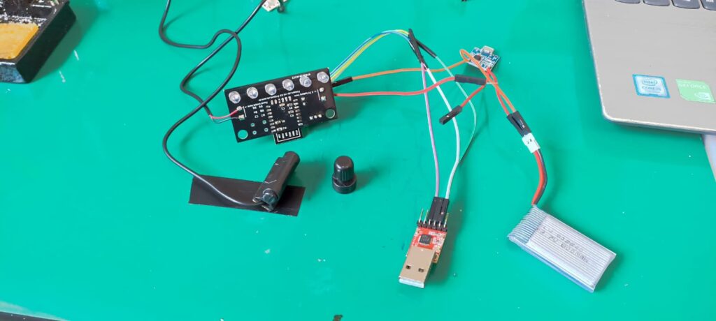
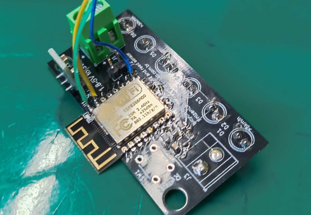
You can seen in the picture above the back side of the PCB, almost fully assembled. It is still missing a 5.08 screw detachable connector, which is coming to me via mail. It is effectively the last piece missing from this build.
I have already run the Arduino code on its ESP8266MOD, seen that it most likely work. I soldered the reed sensor directly to the PCB and simulated the bicycle wheel with a magnet.
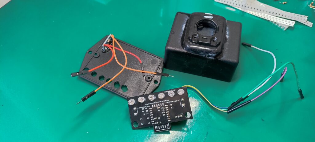
In the pictures above and below you can see the back and front side of the assembled PCB. Along with the designated plastic box and the TP4056 battery charger attached to it.
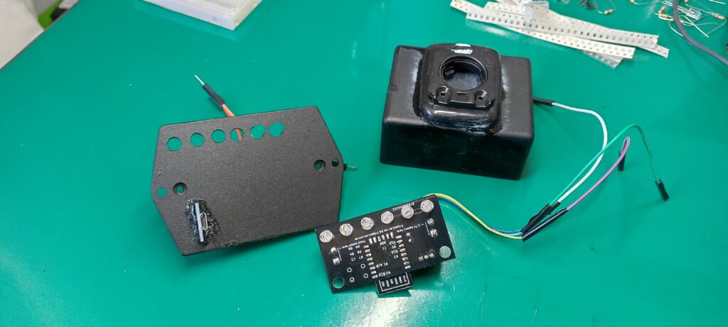
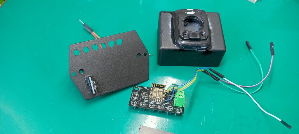
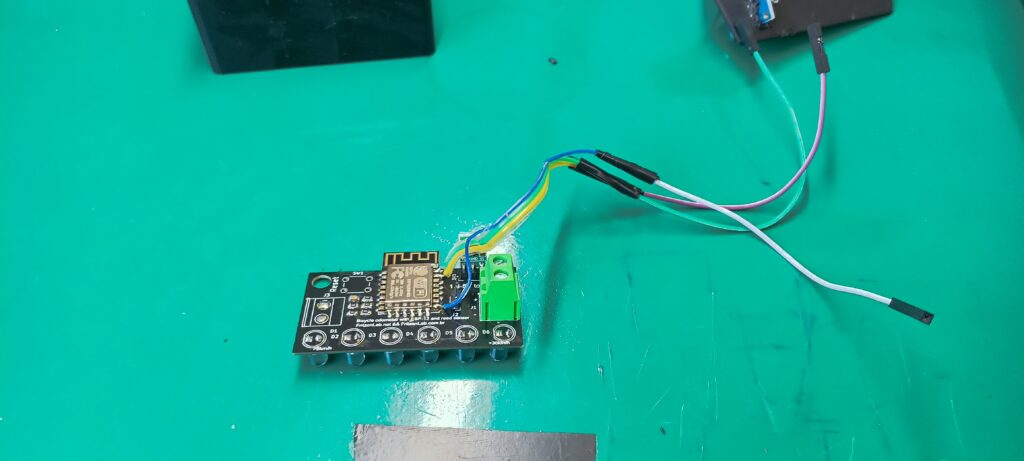
You can notice three wires soldered directly to the PCB: I forgot to add programming circuitry (the ESP8266MOD’s RX and TX lines). I also had to glue a third-party carcass part (from a commercial odometer), so that I can slide my speedometer in and out of the bicycle.
I bought this one from Aliexpress, for parts. This is since I decided to accomodate my speedometer project on a small flat commercial box, like this one.
Final words
Next post will most likely be with results about the speedometer project usage. As the main project page states the ideia is to display speed in km/h in increments of 5km/h, lighting each one of the 6 LEDs accordingly. I plan to make is self-contained, never having to open the project box for anything.
Except maybe for programming, which won’t be necessary as soon as the project is functionality-stable.


Leave a Reply