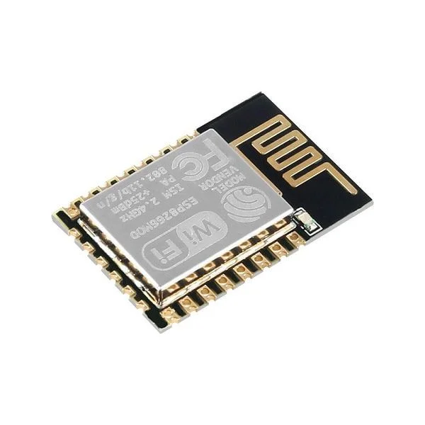
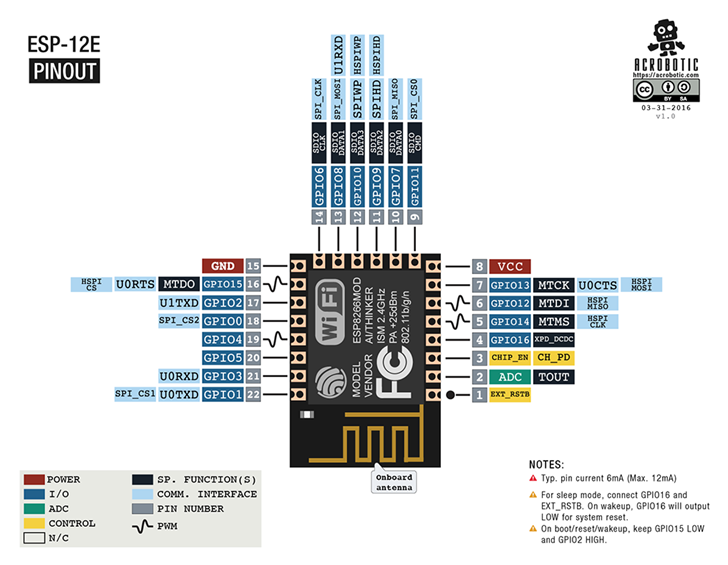
I started coding for my Bicycle speedometer with ESP12. The idea of the code is to light a single LED for every 5km/h increase in speed. So >5km/h lights LED1, > 10km/h lights LED2 and >30km/h lights LED6. And so on. I will be using a ESP8266MOD as the controller, whose image and pins are below.
While testing the code I wrote (which you will se in a minute) I figure that the pins I am using for the LED charlieplexing (12, 13 and 14) all have optional internal pull-ups. I went after this piece of knowledge because I was having more than one LED light sometimes. And that is not what I programmed the code to behave like.
This table gave it away, the “Extendable GPIO” column cites internal pull-ups. For testing on an external nodeMCU I was using pins 0, 4 and 5 for the charlieplexed LEDs. So noticing the erratic behaviour cited above. I then moved away from pin 0 and started using pin 12, the problems seemed to go away.
Now, then internal pull-ups have to be activated, at least is what says here. So an interference from those pull-ups in my charlieplexing is indeed very unlikely. I then moved to use in the test nodeMCU the same pins I will be using in the real thing with a ESP8266MOD. The problem does not show in here, so indeed the pull-ups are only present if you activate them. Not bad.
The code
I made my code without the use of any delay() (of course), all I do is to keep track of the current micros(). I then enter the necessary functions in the time required, not blocking anybody. Since I am not using any high-time-consuming functions (like LCD, i2c, SPI, serial) things are a bit easier to keep track of.
I made a master if conditional for every 5ms, in which I read the reed sensor input. Then I keep track of when every signal rise happens to be able to calculate time between reed sensors activations. Thus created a variable that only let’s the speed calculation happen once per reed activation.
First I calculate the speed in meters per seconds, simply dividing distance (the bicycle wheel radius, in meters) over time. This is the time I kept track of in the last paragraph, already divided by 1000 because it comes from millis() but I need it in seconds. I then obtain the speed in kilometers per hour by multiplying the m/s one by 3.6.
The km/h speed float variable goes through a series of if conditions every 250ms, to separate it in 5km/h parts. Example: it falls into the first if when the speed is over 5km/h. It will get to the last if when the speed is over 30km/h. Every one of this if whill call the ledon(x) function, where ‘x’ is between 0 and 6.
Inside ledon() there are more if conditions to decide what to do with every incoming number, which LED to light. It does this by controlling three output ports to be either output value 0, output value 1 or input. So every 250ms there is a (potential) change in the LED which is lit, depending on which number the ledon(x) function will bring.
For lowering power consumption there is a protecting which turns all LEDs off. It is triggered by the lack of reed sensor activations for more than three seconds.
// First thing, install the ESP8266 support on the Arduino IDE,
// with a link from here https://blog.eletrogate.com/nodemcu-esp12-usando-arduino-ide-2/

// board pinout for Wemos D1 https://forum.arduino.cc/t/weird-wemos-d1-r1/920394/29?page=2
// board pinout for NodeMCU V3 https://cyberblogspot.com/nodemcu-v3-esp8266-pinout-and-configuration/

#include <ESP8266WiFi.h> // just to turn WiFi off, info from here https://arduino.stackexchange.com/questions/43376/can-the-wifi-on-esp8266-be-disabled

// for light sleep woken by a GPIO, I used this reference https://efcomputer.net.au/blog/esp8266-light-sleep-mode/
// there is also something here https://kevinstadler.github.io/notes/esp8266-deep-sleep-light-sleep-arduino/

#define led_a 14 // charlieplex pin 1
#define led_b 12 // charlieplex pin 2
#define led_c 13 // charlieplex pin 3
#define sensor 16 // reed sensor

// Required for LIGHT_SLEEP_T delay mode
/*extern "C" {
  #include "user_interface.h"
  #include "gpio.h"
}*/

long currenttime;
long oldtime;
int sleepcounter;
bool previoussensorstatus;
long timeelapsed;
long previoustime;
float speedms;
float speedkmh;
float wheelperimeter= 2.0 * 3.14159265 * 0.365; // perimeter= 2 * pi * radius
int calldisplaycounter;
int requiredled;
int zerospeedcounter;
int callserialprint;
int contador;

/*void light_sleep(){
   wifi_station_disconnect();
   wifi_set_opmode_current(NULL_MODE);
   wifi_fpm_set_sleep_type(LIGHT_SLEEP_T); // set sleep type, the above    posters wifi_set_sleep_type() didnt seem to work for me although it did let me compile and upload with no errors
   wifi_fpm_open(); // Enables force sleep
   gpio_pin_wakeup_enable(GPIO_ID_PIN(4), GPIO_PIN_INTR_HILEVEL); // GPIO_ID_PIN(2) corresponds to GPIO2 on ESP8266-01 , GPIO_PIN_INTR_HILEVEL for a logic HIGH, can also do other interrupts, see gpio.h above
   //gpio_pin_wakeup_enable(4, GPIO_PIN_INTR_HILEVEL);
   wifi_fpm_do_sleep(0xFFFFFFF); // Sleep for longest possible time
 }*/

void ledon(int requiredled){
  //Serial.println("entrei");
  switch (requiredled) {
  case 0:
    pinMode(led_a, INPUT);
    pinMode(led_b, INPUT);
    pinMode(led_c, INPUT);
    //digitalWrite(led_a, LOW);
    //digitalWrite(led_b, LOW);
    //digitalWrite(led_c, LOW);
    break;
  case 1:
    pinMode(led_a, OUTPUT);
    pinMode(led_b, OUTPUT);
    pinMode(led_c, INPUT);
    digitalWrite(led_a, HIGH);
    digitalWrite(led_b, LOW);
    //digitalWrite(led_c, LOW);
    break;
  case 2:
    pinMode(led_a, OUTPUT);
    pinMode(led_b, OUTPUT);
    pinMode(led_c, INPUT);
    digitalWrite(led_a, LOW);
    digitalWrite(led_b, HIGH);
    //digitalWrite(led_c, LOW);
    break;
  case 3:
    pinMode(led_a, INPUT);
    pinMode(led_b, OUTPUT);
    pinMode(led_c, OUTPUT);
    //digitalWrite(led_a, LOW);
    digitalWrite(led_b, HIGH);
    digitalWrite(led_c, LOW);
    break;
  case 4:
    pinMode(led_a, INPUT);
    pinMode(led_b, OUTPUT);
    pinMode(led_c, OUTPUT);
    //digitalWrite(led_a, LOW);
    digitalWrite(led_b, LOW);
    digitalWrite(led_c, HIGH);
    break;
  case 5:
    pinMode(led_a, OUTPUT);
    pinMode(led_b, INPUT);
    pinMode(led_c, OUTPUT);
    digitalWrite(led_a, HIGH);
    //digitalWrite(led_b, LOW);
    digitalWrite(led_c, LOW);
    break;
  case 6:
    pinMode(led_a, OUTPUT);
    pinMode(led_b, INPUT);
    pinMode(led_c, OUTPUT);
    digitalWrite(led_a, LOW);
    //digitalWrite(led_b, LOW);
    digitalWrite(led_c, HIGH);
    break;
  default:
    // comando(s)
    break;
}
}
void setup() {
  // put your setup code here, to run once:
  Serial.begin(9600);
  WiFi.mode(WIFI_OFF); // turn off wifi

  pinMode(sensor, INPUT);
  //gpio_init();

}

void loop() {
  // put your main code here, to run repeatedly:

  currenttime= micros();
  if(currenttime - oldtime > 5000){ //verifies the sensor every 5ms
    oldtime= micros(); // after 5ms have passed, reset the time counter
    zerospeedcounter++;
    if(zerospeedcounter > 600){ // if more than three seconds have passed without sensor detection (less than an avarage of 3km/h)
      speedkmh= 0; // zero the speed variables
      speedms= 0;
      timeelapsed= 0; // zero the last elapsed time
    }
    if(digitalRead(sensor) && !previoussensorstatus){ // if sensor is HIGH and just was LOW
      zerospeedcounter= 0; // if the sensor was detected within 3 seconds, zero the zero speed flag
      timeelapsed= millis() - previoustime; // calculates the elapsed time between now and the last sensor state change
      speedms= wheelperimeter / (timeelapsed / 1000.0); // THIS calculates speed, wheel perimeter over time elapsed between sensor detections. Dividing by 1000 to get seconds
      speedkmh= speedms * 3.6; // converts m/s to km/h and rounds it for displaying
      previoustime= millis(); // reset the previoustime variable to the current millis()
      previoussensorstatus= true; // when the sensor goes to HIGH this variables goes too
    }else if(!digitalRead(sensor) && previoussensorstatus){ // if sensor is LOW and just was HIGH
      previoussensorstatus= false; // when the sensor goes LOW, reset this variable
    }
    // function to call and light the LED display
    calldisplaycounter++;
    if(calldisplaycounter == 50){ // every 250ms
      calldisplaycounter= 0;

      if(speedkmh >= 30){
        ledon(6);
      }else if(speedkmh >= 25){
        ledon(5);
      }else if(speedkmh >= 20){
        ledon(4);
      }else if(speedkmh>= 15){
        ledon(3);
      }else if(speedkmh >= 10){
        ledon(2);
      }else if(speedkmh >= 5){
        ledon(1);
      }else{
        ledon(0);
      }
    }
    /*callserialprint++;
    if(callserialprint == 100){
      callserialprint= 0;
      Serial.println(timeelapsed);
    }*/
  }
}
The power consumption
My initial idea was to have pin 16 be the reed sensor input. This is because I have read that on ESP8266MOD this pin could be used to wake the chip up. In practice this is not enterely true: as seen here and here it should work. But as far as I could figure pin 16 can be used as an OUTPUT to reset the chip and wake it up. Not an input.
The links above show an idea (both the same) on how to make an external signal wake the ESP8266MOD up, but It did not work for me so far. So I set to measure the current of my prototype while no LEDs where lit and with a single LED lit. The nodeMCU board (actually the 5V entering VIN) was consuming 190mA, a lot of current.
I checked the 3V3 pin and it had 1.71V, well below the expected voltage. It is weird because 190mA is not enough to put down the voltage of the nodeMCU onboard LDO regulator, AMS1117-3.3. I then decided not to go further in testing with the nodeMCU, to wait a couple more days for the bicycle speedomeer PCB. Then I could supply the ESP8266MOD directly with 3.3V and further test things.
Of course the nodeMCU also uses the ESP8266MOD chip I will be putting in my PCB, but there is no surrounding circuitry. The only things power-wise I put in the bicycle speedometer PCB was a 3.3V charge pump (buck-boost) and a sigle 100nF decoupling capacitor.
Bicycle speedometer – until next time
With the code ready and half-tested I can now wait a couple more days for the PCB to arrive. My plan is to assemble the first one already ready to be put in a small box (with detachable reed sensor connector). The box will have three thing facing outside:
- USB connector for battery charging
- Six (6) LEDs
- Reed sensor two-way detachable connector.
Making the bicycle speedometer box watertight will be the biggest challenge, I may (when the prototype is approved) put a bunch of silicone on its holes and openings. Also the idea is to make it the more detachable possible so I remove it every time I leave the bicycle. See you next time.


Pingback: Bicycle odometer project - update 2 - FritzenLab electronics
Pingback: Bicycle odometer project – update 3 - FritzenLab electronics