We will be talking about the rotary Encoder ky-040, a cheap encoder that can be used as a potentiometer to “select” things with Arduino. The code implementation will be “simple” and incomplete, in the sense that there will not be interrupts.
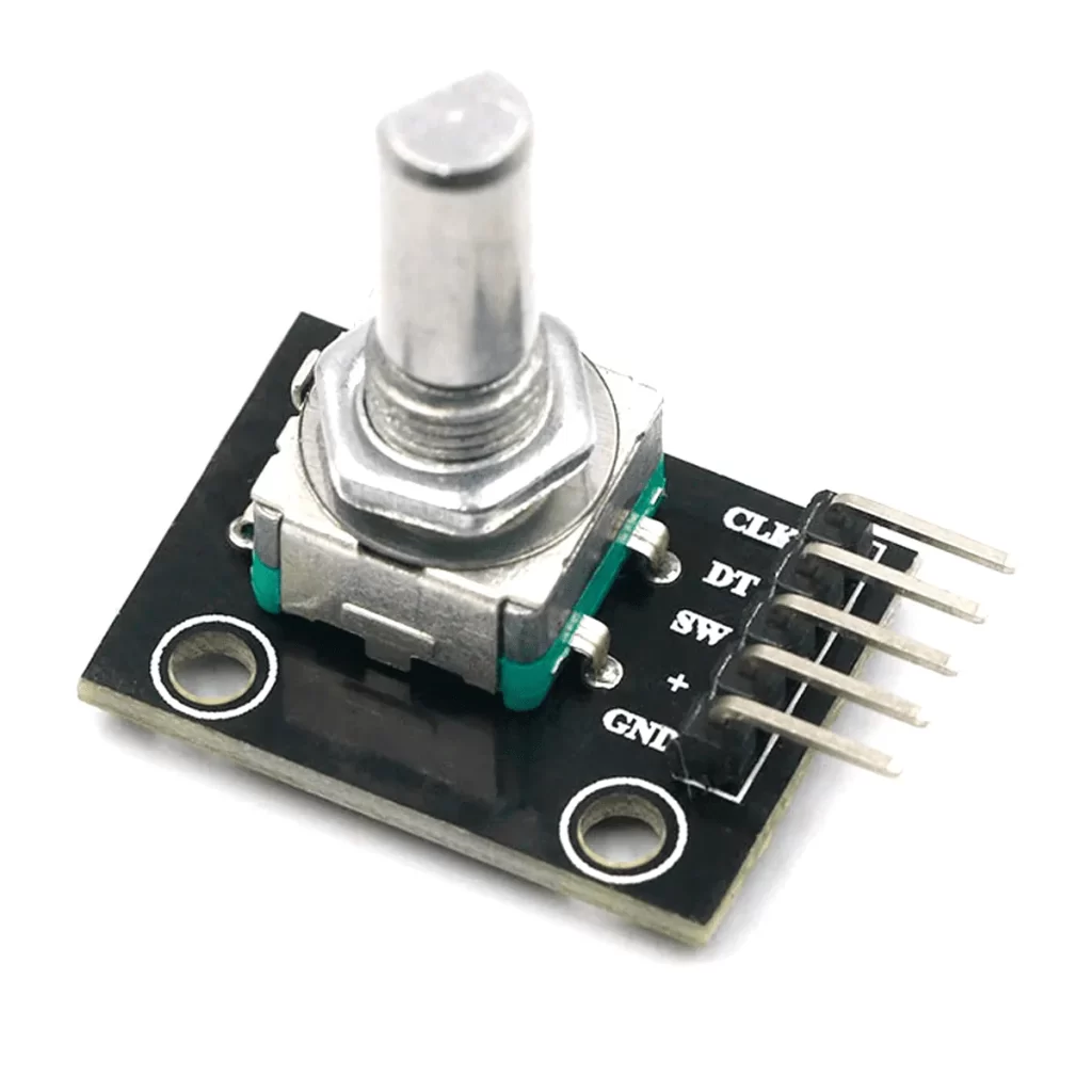
One of the steps in the journey to leave Arduino behind is to write driver code on our own. Code that serves for pheripherals like this rotary encoder. Its datasheet (here) states that it has two signals, CLK and DT. These signals are shifted between them, meaning one occurs first and then the next comes.
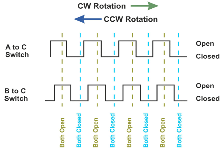
The way we know which direction the rotary encoder is going is by observing which signal comes first. The ideia is simples, just monitor two Arduino digital inputs and see which comes “first”. For simplicity and the sake of showing an idea, I will not be implementing the push button this rotary encoder has in it.
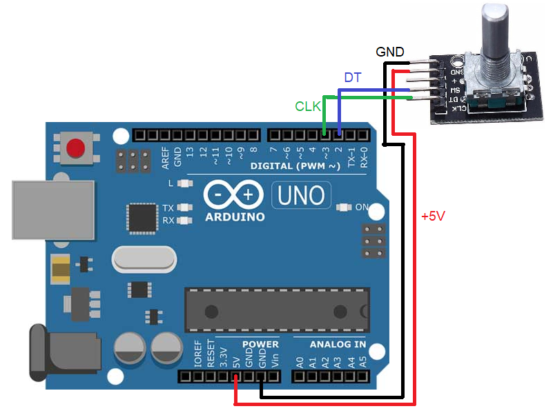
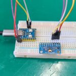
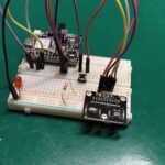
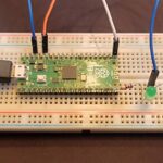
The circuit
It is pretty straight forward, supply +5V and GND to the rotary encoder. Then connect pin DT to Arduino pin 2 and pin CLK to Arduino pin 3. Could be any pin that can do digital input, really.
The code
The code below is my own, I did not take any idea from anywhere else. Just me, the datasheet of the rotary encoder and my computer. The way I like to get things done. Operation theory is according to the exposed above, detect which signal comes first and then next. And act on it.
#define clk 3
#define dt 2
#define led 13

unsigned long oldtime;
unsigned long currenttime;
bool oldclk= false;
bool clkactivated= false;
bool olddt= false;
bool dtactivated= false;
bool possibledt= false;
bool possibleclk= false;
int counter;
int oldcounter;
int enterprint= 0;

void setup() {
  // put your setup code here, to run once:
  pinMode(clk, INPUT);
  pinMode(dt, INPUT);
  pinMode(led, OUTPUT);
  Serial.begin(9600);

}

void loop() {
  // put your main code here, to run repeatedly:
  currenttime= micros();
  if(currenttime - oldtime > 5000){ //5 milisseconds
    oldtime= micros();

    if(digitalRead(clk) && !oldclk){ //if clk is HIGH and oldclk is LOW, clk was clicked
      oldclk= true;
      clkactivated= true;
    }else if(!digitalRead(clk) && oldclk){ //if clk is LOW and oldclk is HIGH, zero oldclk
      oldclk= false;
      clkactivated= false;
    }
    if(digitalRead(dt) && !olddt){ //if clk is HIGH and oldclk is LOW, clk was clicked
      olddt= true;
      dtactivated= true;
    }else if(!digitalRead(dt) && olddt){ //if clk is LOW and oldclk is HIGH, zero oldclk
      olddt= false;
      dtactivated= false;
    }
    if(oldclk && !olddt){ //if clk is HIGH and olddt is LOW
      possibleclk= true; //possibly oldclk is leading
      possibledt= false;
    }else if(oldclk && olddt && possibleclk){ //when clk is HIGH, dt is HIGH and possibleclk is HIGH, clk is leading
      possibleclk= false;
      counter++;
    }
    if(olddt && !oldclk){ //if dy is HIGH and oldclk is LOW
      possibledt= true; //possibly olddt is leading
      possibleclk= false;
    }else if(olddt && oldclk && possibledt){ //when dt is HIGH, clk is HIGH and possibledt is HIGH, dt is leading
      possibledt= false;
      counter--;
    }
    enterprint++;
    if(enterprint== 60){ //Enter print funcion every 300ms (60x 5ms)
      enterprint= 0;
      if(oldcounter == counter){
      //if the numbed in counter did not change, does nothing
      }else{ //if the counter have changed, print the new one
        oldcounter= counter;
        Serial.println(counter);
      }
    }
  }
}
Explaining it a bit to you is necessary, as for example in the edge detection code. I wrote the piece below to inform me when a signal was LOW and is now HIGH. This is a simple way of detecting an edge (in this case the rising one, which I have implementented already here).
if(digitalRead(clk) && !oldclk){ //if clk is HIGH and oldclk is LOW, clk was clicked
      oldclk= true;
      clkactivated= true;
    }else if(!digitalRead(clk) && oldclk){ //if clk is LOW and oldclk is HIGH, zero oldclk
      oldclk= false;
      clkactivated= false;
    }
The code above also detects the falling edge, when the signal goes from HIGH to LOW. The second part of the code is deciding who came first, I do this with the piece of code below. if one singal is HIGH and the other LOW I set (for example) possibleclk= true.
Then when the signal that was LOW goes to HIGH and the former is still HIGH, I detect that the first one came first. This is the juice of this post. Notice in the complete code above that I do edge detection and sequence detection twice, once for each input. This is independently and interleaved.
if(oldclk && !olddt){ //if clk is HIGH and olddt is LOW
      possibleclk= true; //possibly oldclk is leading
      possibledt= false;
    }else if(oldclk && olddt && possibleclk){ //when clk is HIGH, dt is HIGH and possibleclk is HIGH, clk is leading
      possibleclk= false;
      counter++;
    }
The end result commented
I have run the complete code with the schematics above and obtained the result below, in the Arduino serial monitor. What I am doing is to turn the encoder step by step in both directions.
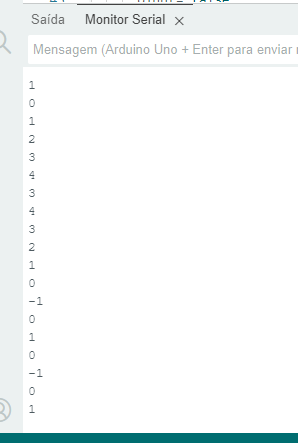
Turning the encoder to one side adds to the variable shown in the screen, while turning to the other side substracts from it. There is a single bug visible in this stream, in the part 2 3 4 3 4 3 2 there should not be the 3 4 in the middle. It should be 2 3 4 3 2.
This could be due to the fact that we are calling Serial.println() every 300 ms, and it blocks the entire code while executes. After all I have not implemented this code with interrupts, so this could totally happen.
Final words
All code implemented here is just for fun, despite the idea being correct the implementation lacks protections and verifications. Interrupts are the way to go when coding for time-sensitive components like this rotary encoder.

Leave a Reply