Another update on my bicycle odometer project, to tell you I have finished editing the schematic diagram and routing the printed circuit board. As we have previously seen here and here, I am on my way designing a bicycle odometer/speedometer.
I have now settled on the controller, which will be the ESP-12 and also on the power supply side. It will comprise a 3.7V Lithium battery, a TP4056 for battery charging and a regulates charge pump module with the HX4002B chip, as found in Aliexpress.
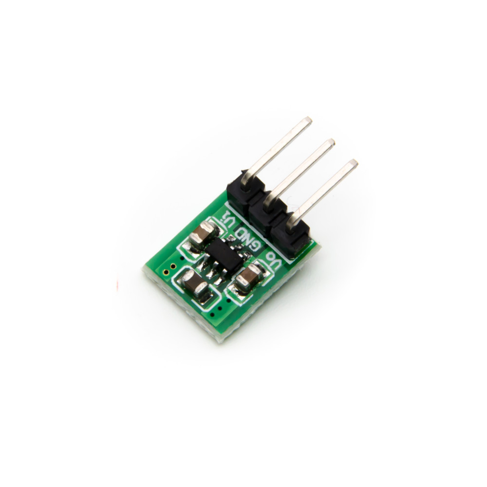
According to its datasheet, the HX4002B can handle 150mA in 3.3V while accepting input voltages between 1.8V and 5.5V. I have not tested it yet, but researching the ESP-12 current consumption (75mA) I think the HX4002B will be able to handle it.
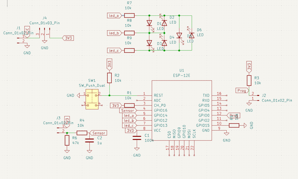
The schematic and board layout
From the last update what I have changed the most in the schematic was to remove the AMS1117-3.3 and add the HX4002B. Besides that I finished routing and addind silk-screen to the PCB, as seen below.
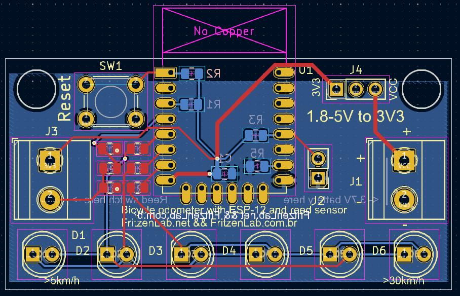
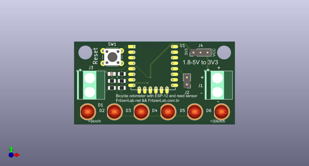
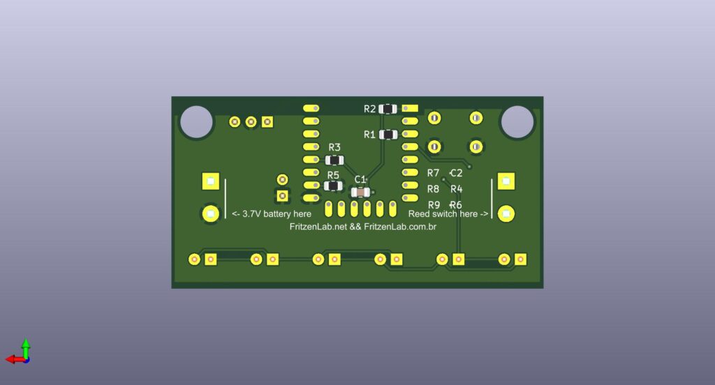
Notice a bit of details: I have added silk-screen to the back of the board indicating where does the reed switch go and also the power supply (battery). There are indications of which speed turns which LED on, specially the 5km/h and 30km/h marks.
As stated previously, there is a jumper (J2) for for ESP-12 programming and also a physical reset button. This bicycle odometer project is turning out to be a nice little challenge for me, thinking about a minimal circuit that can still do its job.
Future work
Next step will be ordering the fabrication of the printed circuit board, probably on PCBWAY because I have some credit in there yet. I also plan to prototype the circuit in perfboard, just to start writing some software for it.


i came looking for HX4002B .. tested it out with PN532.. works like charm!