A quick update on the bicycle odometer project, I have now decided on every component of it. Have even made an atttempt on the printed circuit board layout.
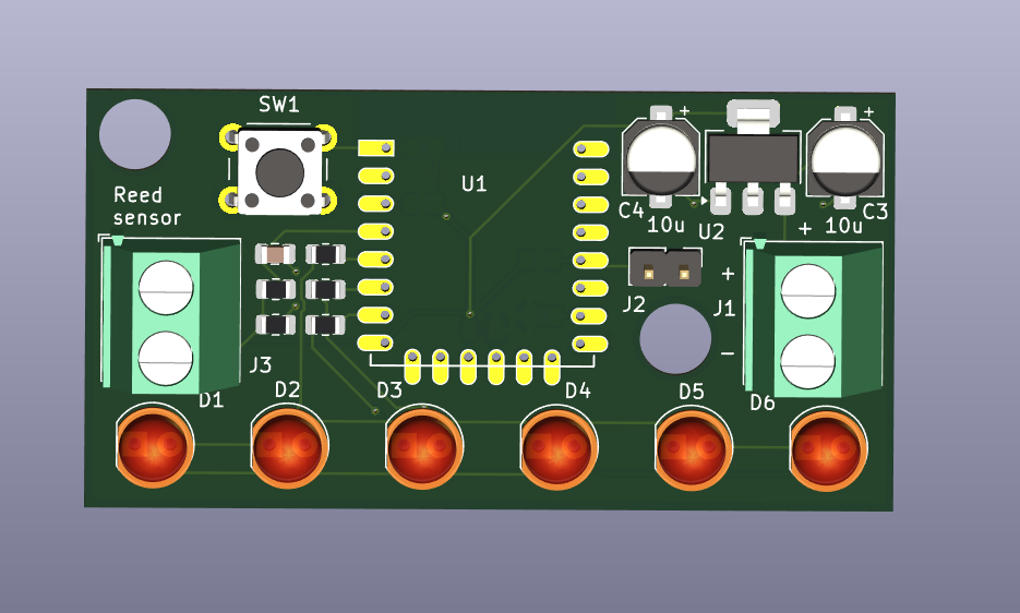
The board features an ESP-12 (ESP8266) because this is what I have in my hands right now, have a bunch of it. There is the jumper J2 for entering the chip programming mode and the push button SW1 for reset.
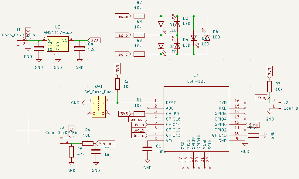
There are two 5.08mm connectors onboard: one for the reed sensor and the other for the VIN. Speaking of which, VIN has to be a voltage greater than 3,3V. At this moment I realized a mistake I made: the drop out voltage of AMS1117-3.3 I am using is around 1.2-1.5V, so it would not work with a battery voltage smaller than 4.5V.
Means I cannot use the AMS1117-3.3 for this project. It is back to the drawing board. There are a bunch of buck-boost options like this ones on Aliexpress, maybe that’s the way.
Besides that, there are six LEDs in charlieplex mode to make for the speed display. Each LED will represent 5km/h increments, so for example 3 lit LEDs will tell us the speed is over 15km/h. Each ESP-12 pin which goes to the LEDs has a resistor in series, for current limiting.
There are four resistors and a capacitor that are mandatory in the design, for the ESP-12.
Three of the resistors pull the reset, prog and CH_PD pins high, while the fourth one pulls GPIO15 low. The 100nF ceramic capacitor is used for power supply decoupling.
To wrap up this update
I will have to think through the power supply stuff, since the ESP-12 will only take 3.3V flat as power supply. I will also give it a thought about using WiFi to connect to a cellphone for speed data.


Pingback: Bicycle odometer project – update 3 - FritzenLab electronics