Today we will learn how to use the 433Mhz transmitter and receiver set with Arduino. This wireless transmission technology is widely used in electronic gate remote controls. Most of the information in the first part of the article was taken from here.
The library we will initially use is the RC-switch available here. Download the library from the link and then, in the Arduino IDE, go to “Sketch > Include library > Add .ZIP library”. Within the files you downloaded there will be a file called “output.ino”, place this file in the same folder where you save the sketch of the code below.
/*
  Example for receiving

  https://github.com/sui77/rc-switch/

  If you want to visualize a telegram copy the raw data and
  paste it into http://test.sui.li/oszi/
*/

#include <RCSwitch.h>

RCSwitch mySwitch = RCSwitch();

void setup() {
  Serial.begin(9600);
  mySwitch.enableReceive(0);  // Receiver on interrupt 0 => that is pin #2
}

void loop() {
  if (mySwitch.available()) {
    output(mySwitch.getReceivedValue(), mySwitch.getReceivedBitlength(), mySwitch.getReceivedDelay(), mySwitch.getReceivedRawdata(),mySwitch.getReceivedProtocol());
    mySwitch.resetAvailable();
  }
}
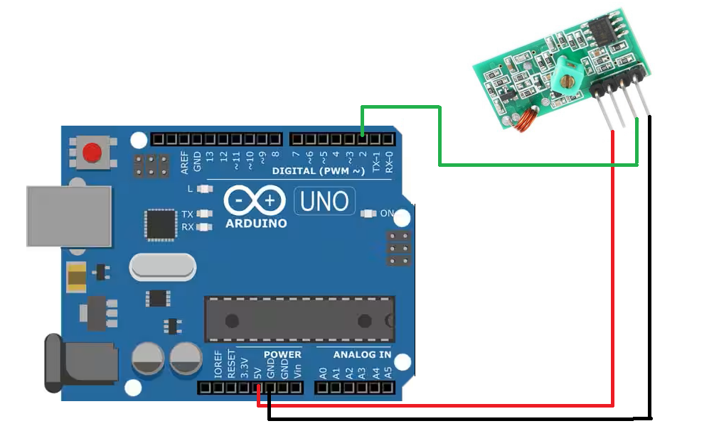
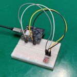
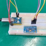
mySwitch.getReceivedValue()The RF receiver will be connected to Arduino pin 2, interrupt 0. Our gate remote control will be the emitter. See the connection diagram in the image below.
On the serial monitor, when you press a gate control button, the following is visible:
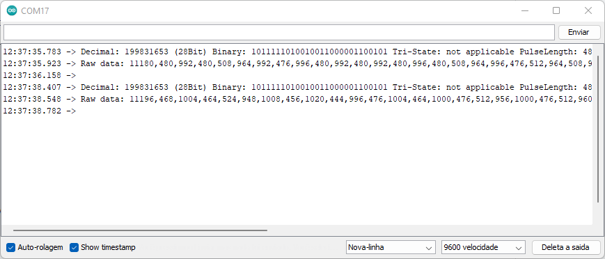
These values (decimal, binary) are unique for each control and can be used to implement the most diverse controls, which is what we are going to do next.
Transmitter and receiver
To work with transmitter and receiver we will use the Radiohead library, as seen in this post and which can be downloaded from here. To install it on your Arduino, in the Arduino IDE go to “Draft > Add library > Add .ZIP library” and look for the file you downloaded from the link above.
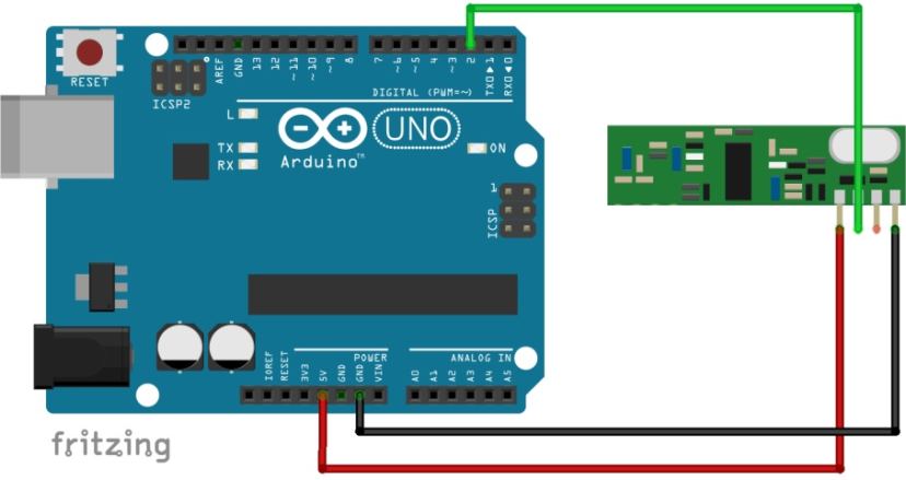
I confess that I didn’t understand why pins 2 and 12 are used, but I imagine it must have something to do with SPI, since these are the Arduino pins for this function. The SPI library is called in the code below, although it is not used.
Copy and paste this code into the Arduino sender:
#include <RH_ASK.h>
#include <SPI.h> // Not actually used but needed to compile

RH_ASK driver;

void setup()
{
    Serial.begin(9600);	  // Debugging only
    if (!driver.init())
         Serial.println("init failed");
}

void loop()
{
    const char *msg = "123456789012";
    driver.send((uint8_t *)msg, strlen(msg));
    driver.waitPacketSent();
    delay(1000);
}
And this code on the Arduino receiver:
#include <RH_ASK.h>
#include <SPI.h> // Not actualy used but needed to compile
RH_ASK driver;
void setup()
{
Serial.begin(9600); // Debugging only
if (!driver.init())
Serial.println("init failed");
}
void loop()
{
uint8_t buf[12];
uint8_t buflen = sizeof(buf);
if (driver.recv(buf, &buflen)) // Non-blocking
{
int i;
// Message with a good checksum received, dump it.
Serial.print("Message: ");
Serial.println((char*)buf);
}
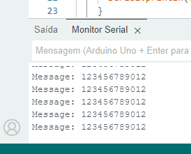
}The result of the receiving code in the Arduino IDE Serial monitor is the message that the sender sent, “123456789012”:
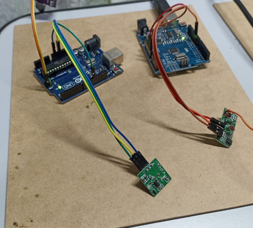
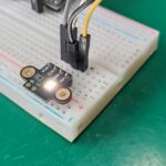
And below is a quick video of how the codes shown above work. Note that the receiver’s antenna may be a small piece of copper wire.
Final words
Something I didn’t comment on was the range of this type of remote control. Electronic gate manufacturers put it at 40 meters, which is a good distance. Another detail is the size of the antenna, which according to this link and this one, should be on average 17cm.
You can do a lot of cool automations with these 433MHz modules, your creativity is the limit. Want to buy the module used in this post? use my affiliate link here.


Leave a Reply