Today we are going to read the NTC thermistor temperature with Arduino. But first let’s define some terms that will be useful throughout the article. Firstly, “thermistor”, which is a resistor whose resistance depends on the temperature to which it is subjected.
Now NTC, which in English means “negative temperature coefficient”. This means that its resistance decreases with increasing temperature, and vice versa. Different from a PTC “positive temperature coefficient”, its resistance increases with increasing temperature.
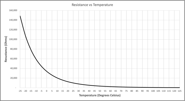
The NTC is widely used in industry as it is a cheap and very reliable sensor, and can be used at temperatures between -55ºC and +200C. The only problem is that its curve is not linear like that of an LM35, it is an exponential curve. This requires an equation to obtain the temperature starting from a resistance value. See image below.
The circuit
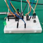
The electronic circuit used in today’s experiment is very simple, you need an NTC thermistor (I took one with 10k Ohm resistance) and another 10k Ohm resistor.
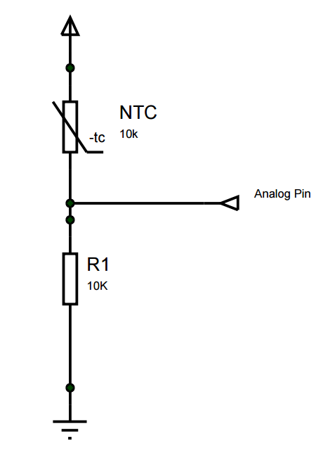
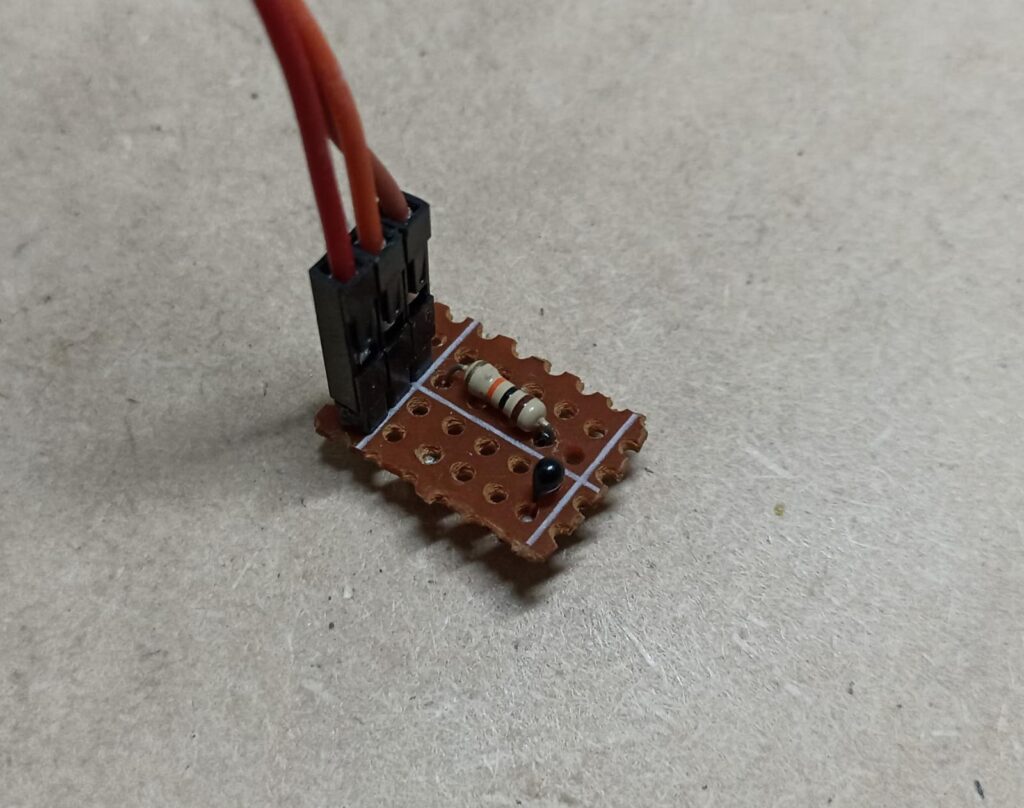
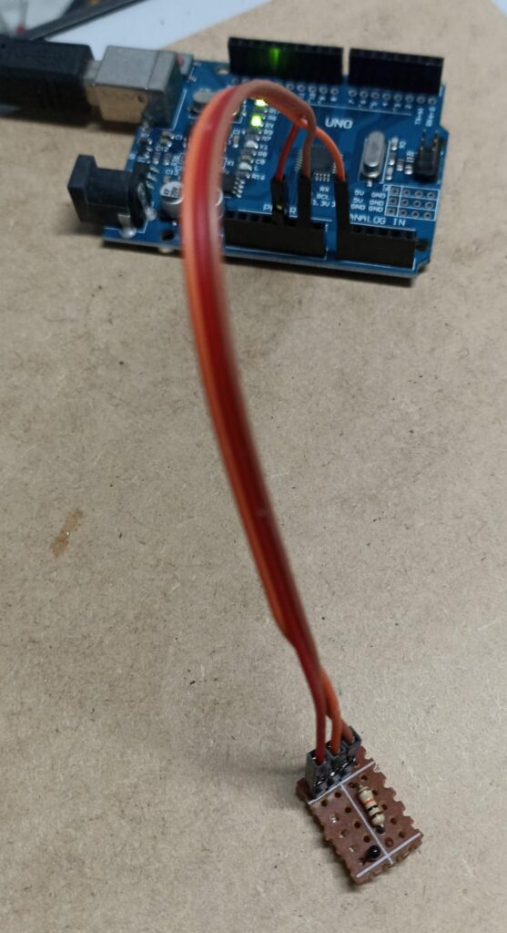
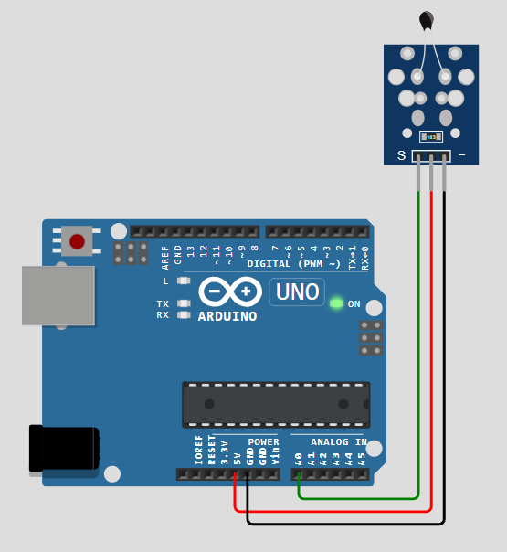
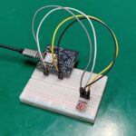
I assembled the circuit above on the plate below, for easy connection to the Arduino. I connected the central point between the two components to the Arduino’s analog input A0. The +Vcc is 5V.
The code below was the first one I used to test the operation of the NTC thermistor, it only reads the analog input A0 and directs the value to the computer’s serial monitor.
// These constants won't change. They're used to give names to the pins used:
const int analogInPin = A0; // Analog input pin that the potentiometer is attached to
int sensorValue = 0; // value read from the pot
void setup() {
// initialize serial communications at 9600 bps:
Serial.begin(9600);
}
void loop() {
// read the analog in value:
sensorValue = analogRead(analogInPin);
// print the results to the Serial Monitor:
Serial.print("sensor = ");
Serial.println(sensorValue);
// wait 2 milliseconds before the next loop for the analog-to-digital
// converter to settle after the last reading:
delay(200);
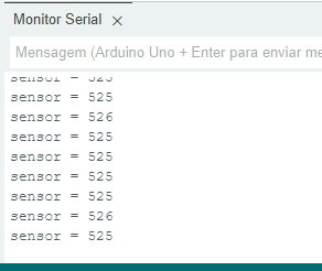
}The analog reading on the serial monitor is as follows. See that the value is between 0 and 1024 (2^10, 10bit)
The code
How to convert this value to temperature? I used code from this reference. The code is below and has some details to be configured:
Code repository here, from Github. Another reference can be found here.
// Fonte: https://www.makerhero.com/blog/termistor-ntc-arduino/
/*
 * Leitura de temperatura usando um termistor
 */

// Conexão do termistor
const int pinTermistor = A0;

// Parâmetros do termistor
const double beta = 3950.0;
const double r0 = 10000.0;
const double t0 = 273.0 + 25.0;
const double rx = r0 * exp(-beta/t0);

// Parâmetros do circuito
const double vcc = 4.92;
const double R = 9810.0;

// Numero de amostras na leitura
const int nAmostras = 5;

// Iniciação
void setup() {
  Serial.begin(9600);
}

// Laço perpétuo
void loop() {
  // Le o sensor algumas vezes
  int soma = 0;
  for (int i = 0; i < nAmostras; i++) {
    soma += analogRead(pinTermistor);
    delay (100);
  }

  // Determina a resistência do termistor
  double v = (vcc*soma)/(nAmostras*1024.0);
  double rt = (vcc*R)/v - R;

  // Calcula a temperatura
  double t = beta / log(rt/rx);
  Serial.println (t-273.0);

  // Dá um tempo entre leituras
  delay (1000);
}
Firstly we need the thermistor beta, which I found on the internet (here) as being 3950, but it may vary depending on the NTC you have on hand. We also have “r0” which is the resistance of the thermistor at 25ºC, in my case it was 10k Ohm. We configured VCC which in our case (on the Arduino) was measured with a multimeter at 4.92V. And finally the “R” series value, which in my case is 9.81k Ohm (also measured with a multimeter).
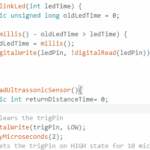
The “magic” of the equation happens in the lines below:
// Get the resistance
double v = (vcc*soma)/(nAmostras*1024.0);
double rt = (vcc*R)/v - R;
// Calculate temperature
double t = beta / log(rt/rx);
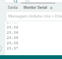
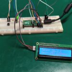
Serial.println (t-273.0);The result of the value read on the serial monitor can be seen below, in degrees Celsius (ºC):
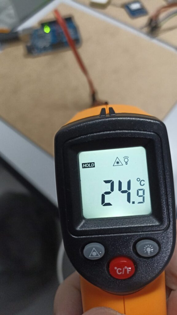
With an external thermometer the temperature over the NTC was a little low, but similar enough:
I also did a simulation in Wokwi, but there the sensor has its resistor inverted, it shows the temperature “in reverse”, it rises when the sensor temperature drops. See the schematic diagram of the simulation below.
Final words
Want to buy some NTC to try it out? use my sponsored link and buy on Banggood. Also discover another temperature sensor, this time integrated, the SHT21 here.


Leave a Reply