We will create an Attiny85 thermometer with binary display using six LEDs. We will use only three microcontroller pins for the six LEDs, using the charlieplexing technique. The temperature sensor will be the DHT11, communicating with the Digispark Attiny85 via a single wire.
Digispark Attiny85 was created by the Digistump group. This group started with a Kickstarter campaign, specifically for the Digispark Attiny85 product. Today the group no longer exists, so the community took over the maintenance of the project. That’s because the Attiny85 is a super useful card, it even has a USB.
I chose the Attiny85 for the binary thermometer project precisely because it is small, has low power consumption and has a sufficient number of pins for what I need. To also buy the board you can access this Aliexpress link. Here is how to use Digispark Attiny85.
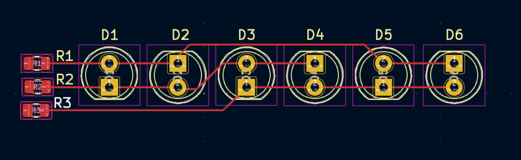
The connection of the six LEDs was inspired by this link, using only three Attiny85 pins. The image below is for reference only.
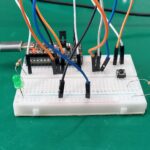
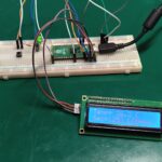
The first prototype of the product is seen below, it was made on a breadboard.
The code
All project code is available here, made for the Arduino IDE. The path to be followed by information in this project is as follows:
- DHT11 sensor reading, returns a float
- Converting float to int (integer)
- Conversion from int to binary (6 bit)
- Transfer of binary information to the corresponding outputs, through charlieplexing
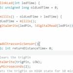
The magic of converting from float to binary occurs in the lines below, where I make a FOR loop with six passes. In each pass, the temperature value “t” is rounded, then converted to an integer and then converted to a bit. Where “i” is the bit control variable.
for (int i = 0; i < 6; i++) {


      bitsresultados[i] = bitRead(int(round(t)), i); //This is where the magic happens, I get the "t" value (temperature),
      // round it, convert it to integer and extract every bit of its binary equivalent. The bits are then used to enter
      // each charlieplexed LED bit value

    }
Then, in another part of the code, each bit is converted to its corresponding value in the charlieplex. In the example below, I turn ON output 2 and turn OFF 3 if bit 5 of bitsresults[] is equal to 1. In this case, output 4 is set as input so as not to interfere with the other two.
if (digitoaentrar == 1 && passagem == 1) {
      if (bitsresultados[5] == 1) {
        pinMode(2, OUTPUT);
        pinMode(3, OUTPUT);
        pinMode(4, INPUT);
        digitalWrite(2, HIGH);
        digitalWrite(3, LOW);
      }
      digitoaentrar = 2;
    }
I do not use the delay() function, so the code is not blocking (it does not stop/freeze between actions it must take). See the full code below.
#include <DHT.h>
#include <DHT_U.h>

// Example testing sketch for various DHT humidity/temperature sensors
// Written by ladyada, public domain

// REQUIRES the following Arduino libraries:
// - DHT Sensor Library: https://github.com/adafruit/DHT-sensor-library
// - Adafruit Unified Sensor Lib: https://github.com/adafruit/Adafruit_Sensor

#include "DHT.h"


#define DHTPIN 1     // Digital pin connected to the DHT sensor
// Feather HUZZAH ESP8266 note: use pins 3, 4, 5, 12, 13 or 14 --
// Pin 15 can work but DHT must be disconnected during program upload.

// Uncomment whatever type you're using!
#define DHTTYPE DHT11   // DHT 11
//#define DHTTYPE DHT22   // DHT 22  (AM2302), AM2321
//#define DHTTYPE DHT21   // DHT 21 (AM2301)

int bitsresultados[6];
int passagem= 0;

// Variables used on this code
unsigned long time1;
unsigned long previousTime;
boolean enterFunction = true;
unsigned long time2;
unsigned long previousTime2;
boolean enterFunction2 = true;
//-----------------------

int digitoaentrar = 1;
float h;
float t;
float f;

// Connect pin 1 (on the left) of the sensor to +5V
// NOTE: If using a board with 3.3V logic like an Arduino Due connect pin 1
// to 3.3V instead of 5V!
// Connect pin 2 of the sensor to whatever your DHTPIN is
// Connect pin 3 (on the right) of the sensor to GROUND (if your sensor has 3 pins)
// Connect pin 4 (on the right) of the sensor to GROUND and leave the pin 3 EMPTY (if your sensor has 4 pins)
// Connect a 10K resistor from pin 2 (data) to pin 1 (power) of the sensor

// Initialize DHT sensor.
// Note that older versions of this library took an optional third parameter to
// tweak the timings for faster processors.  This parameter is no longer needed
// as the current DHT reading algorithm adjusts itself to work on faster procs.
DHT dht(DHTPIN, DHTTYPE);

void setup() {
  dht.begin();
  //Serial.begin(9600);
}

void loop() {

  time1 = micros();
  time2 = micros();
  if (enterFunction == true) {
    previousTime = time1;
    passagem++;
    // Start your code below
    //-----------------------


    if (digitoaentrar == 1 && passagem == 1) {
      if (bitsresultados[5] == 1) {
        pinMode(2, OUTPUT);
        pinMode(3, OUTPUT);
        pinMode(4, INPUT);
        digitalWrite(2, HIGH);
        digitalWrite(3, LOW);
      }
      digitoaentrar = 2;
    }
    if (digitoaentrar == 2 && passagem == 2) {
      if (bitsresultados[4] == 1) {
        pinMode(2, OUTPUT);
        pinMode(3, OUTPUT);
        pinMode(4, INPUT);
        digitalWrite(2, LOW);
        digitalWrite(3, HIGH);
      }
      digitoaentrar = 3;
    }
    if (digitoaentrar == 3 && passagem == 3) {
      if (bitsresultados[3] == 1) {
        pinMode(2, INPUT);
        pinMode(3, OUTPUT);
        pinMode(4, OUTPUT);
        digitalWrite(3, HIGH);
        digitalWrite(4, LOW);
      }
      digitoaentrar = 4;
    }
    if (digitoaentrar == 4 && passagem == 4) {
      if (bitsresultados[2] == 1) {
        pinMode(2, INPUT);
        pinMode(3, OUTPUT);
        pinMode(4, OUTPUT);
        digitalWrite(3, LOW);
        digitalWrite(4, HIGH);
      }
      digitoaentrar = 5;
    }
    if (digitoaentrar == 5 && passagem == 5) {
      if (bitsresultados[1] == 1) {
        pinMode(2, OUTPUT);
        pinMode(3, INPUT);
        pinMode(4, OUTPUT);
        digitalWrite(2, HIGH);
        digitalWrite(4, LOW);
      }
      digitoaentrar = 6;
    }
    if (digitoaentrar == 6 && passagem == 6) {
      if (bitsresultados[0] == 1) {
        pinMode(2, OUTPUT);
        pinMode(3, INPUT);
        pinMode(4, OUTPUT);
        digitalWrite(2, LOW);
        digitalWrite(4, HIGH);
      }
      digitoaentrar= 1;
      passagem= 0;
    }

    //-----------------------
    // End of your code
  }

  if (enterFunction2 == true) {
    previousTime2 = time2;

    // Reading temperature or humidity takes about 250 milliseconds!
    // Sensor readings may also be up to 2 seconds 'old' (its a very slow sensor)
    //h = dht.readHumidity();
    // Read temperature as Celsius (the default)

    t = dht.readTemperature();
    // Read temperature as Fahrenheit (isFahrenheit = true)
    //f = dht.readTemperature(true);

    for (int i = 0; i < 6; i++) {


      bitsresultados[i] = bitRead(int(round(t)), i); //This is where the magic happens, I get the "t" value (temperature),
      // round it, convert it to integer and extract every bit of its binary equivalent. The bits are then used to enter
      // each charlieplexed LED bit value

    }
   /* // Check if any reads failed and exit early (to try again).
    if (isnan(h) || isnan(t) || isnan(f)) {
      Serial.println(F("Failed to read from DHT sensor!"));
      return;
    }*/

    /*// Compute heat index in Fahrenheit (the default)
    float hif = dht.computeHeatIndex(f, h);
    // Compute heat index in Celsius (isFahreheit = false)
    float hic = dht.computeHeatIndex(t, h, false);*/


  }


  // The DELAY time is adjusted in the constant below >>
  if (time1 - previousTime < 990) { // 1 million microsencods= 1 second delay
    /* I have actually used 0.999990 seconds, in a trial to compensate the time that
       this IF function takes to be executed. this is really a point that
       need improvement in my code */
    enterFunction = false;
  }
  else {
    enterFunction = true;
  }
  if (time2 - previousTime2 < 4999990) { // 1 million microsencods= 1 second delay
    /* I have actually used 0.999990 seconds, in a trial to compensate the time that
       this IF function takes to be executed. this is really a point that
       need improvement in my code */
    enterFunction2 = false;
  }
  else {
    enterFunction2 = true;
  }

}
The schematic diagram
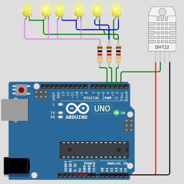
I simulated the Attiny85 thermometer in Wokwi, but it doesn’t work properly due to (I imagine) setting the pins as input at run time. The schematic diagram is also seen below, using Arduino as Wokwi does not have a Digispark Attiny85. The pins are the same:
- Pin 1 for DHT11 sensor
- Pins 2, 3 and 4 for the six LEDs
The workings of it
The DHT11 is read every five seconds, while each LED is updated every 1 millisecond. This is to give the impression that they are all turned on at the same time, while in reality only one is turned on at a time. This is the basic precept of charlieplexing.
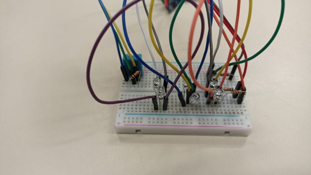
Below is an image of the almost finished circuit, showing how to read the temperature using the LEDs.
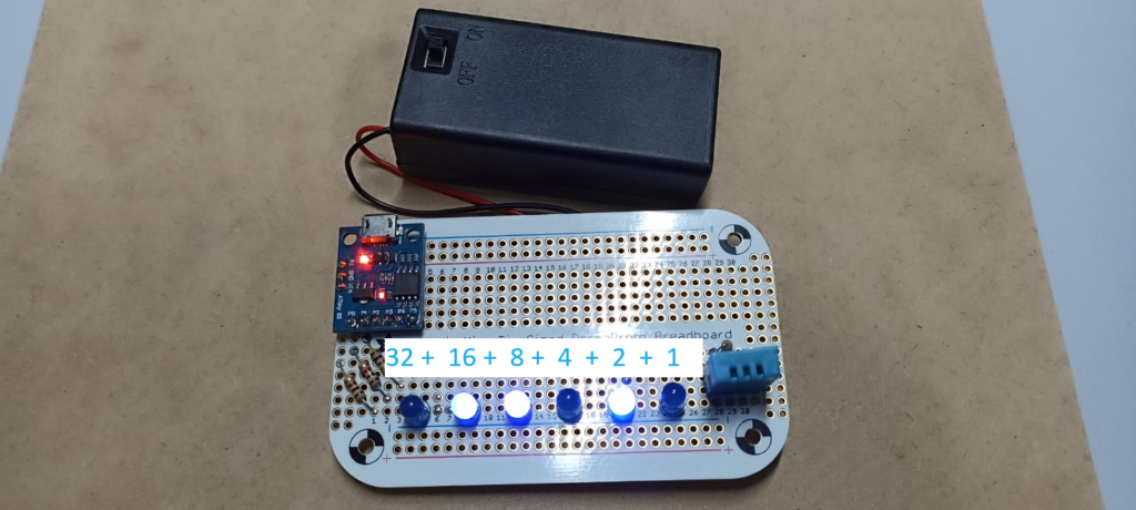
In the image above, the second (2^4), third (2^3) and fifth (2^1) LEDs are on, giving us 16+8+2= 26ºC. It is very simple to read in binary, just add the value assigned to the energized LEDs.
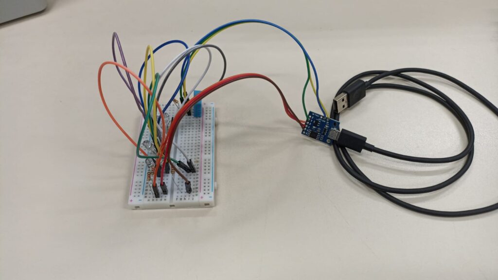
I used a 9V battery to supply the circuit directly on the VIN pin of the Digispark Attiny85 board, without filtering or anything.
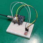
Below is an image of the final product, with the battery clip already glued to the prototype board. Remember that all the code and schematic diagram are available on my Github, here.
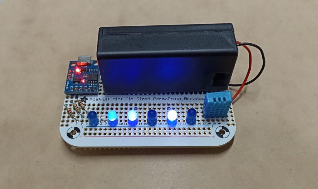
Note: the temperature shown above is also 26ºC, since LEDs two (2^4), three (2^3) and five (2^1) are energized: 16+8+2= 26ºC.


Leave a Reply